
Author: kevin

  • 12-Bit Second BCH Error Correcting Field (Bits 133 – 144)

    The 26 bits forming the second protected data field (PDF-2, bits 107 to 132) are followed by a 12-bit Bose-Chaudhuri-Hocquenghem (BCH) error-correcting code, in a field defined as the second BCH error correcting field (BCH-2, bits 133 to 144). This code can detect and correct up to two bit errors in the 38 bits of the second protected field (SPF=PDF-2 + BCH-2). The error-correcting code is generated from the content of PDF-2 as described in Annex B of Cospas-Sarsat Beacon Specification C/S T.001 (click here to download a copy of document C/S T.001 in PDF format). Therefore, it must be computed and encoded together with the PDF-2.

    In the case of location protocol beacons, when updates to the PDF-2 are required for encoding position data, the error-correcting code (BCH-2) must be regenerated after each update.

    The 12-bit BCH error-correcting code must be computed and encoded in the second BCH error correcting field (BCH-2) of all protocols using the long message format (with the exception of orbitography protocol which are intended for use only by the Cospas-Sarsat System operators).

    The terminology used in Cospas-Sarsat to define the second protected field (SPF), the second protected data field (PDF-2) and second BCH error correcting field (BCH-2) is illustrated above.

  • 21-Bit First BCH Error Correcting Field


    21-Bit First BCH Error Correcting Field (Bits 86 – 106)

    The 61 bits forming the first protected data field (PDF-1, bits 25 to 85) are followed by a 21-bit Bose-Chaudhuri-Hocquenghem (BCH) error-correcting code, in a field defined as the first BCH error correcting field (BCH-1, bits 86 to 106). This code can detect and correct up to three bit errors in the 82 bits of the first protected field (FPF=PDF-1 + BCH-1). The error-correcting code is generated from the content of PDF-1 as described in Annex B of document C/S T.001 “Cospas-Sarsat Beacon Specification”. Therefore, it must be computed and encoded together with the PDF-1.

    In the case of location protocol beacons, when updates to the PDF-1 are required for encoding position data, the error-correcting code (BCH-1) must be regenerated after each update.

    The terminology used by Cospas-Sarsat to define the first protected field (FPF), the first protected data field (PDF-1) and first BCH error correcting field (BCH-1) is illustrated above.

  • Position Data Source

    Bits Meaning
    0 Encoded position data is provided by an external navigation device.
    1 Encoded position data is provided by an internal navigation device.


  • Activation Code (Bit 108)

    Bit 108 in User protocols indicate the method of activation that has been built into the beacon. A “0” indicates that the beacon is a type that can only be activated manually, whereas “1” indicates that the beacon can be activated both manually and automatically.

    activation


  • Identification or Identification Plus Position Data (Bits 37 – 85)

    The content of these bits are determined by the protocol selected. These bits when combined with the protocol flag (bit 26) and the country code (bits 27 – 36) form the unique identification of the beacon. The hexadecimal representation of bits 26 – 85 is referred to as the beacon 15 Hex ID. It is critical that every beacon’s 15 Hex ID be unique.


  • Country Code (Bits 27 – 36)

    The country code is part of every beacon message protocol. This code is a 3-digit decimal number allocated to each country/territory by the International Telecommunication Union (ITU) and listed as Maritime Identification Digits (MID) in Appendix 43 of the ITU Radio Regulations. The up-to-date list of MIDs is available from the ITU web site at:

    https://www.itu.int/en/ITU-R/terrestrial/fmd/Pages/mid.aspx

    The country code is encoded in binary notation in bits 27 to 36 of the message, with the least significant bit on the right. The country code always indicates the country of beacon registration. Upon receiving distress alerts, SAR services will endeavor to obtain additional information on the owner of the distress beacon using the MID to interrogate the appropriate beacon registration database.

    The example presented below shows the country code for the United Kingdom, where: MID=232 (i.e. decimal number “232” coded “0011101000” in binary notation).

    Bits

    27—————–36


    0 0 1 1 1 0 1 0 0 0


  • Protocol Flag (Bit 26)

    The protocol type is identified at bit 26 for all message formats. All User protocols, including the User Location Protocol, are indicated with a “1” in bit 26. All Location protocols, with the exception of the User Location Protocol, are indicated by a “0” in bit 26.

    P=0 Standard Location Protocol or National Location Protocol
    P=1 User Protocol or User Location Protocol


  • Format Flag (Bit 25)

    The beacon message format is identified at bit 25 for all message formats. A “0” in bit 25 indicates a short format message which will transmit 112 data bits in each burst. A “1” in bit 25 indicates a long format message which will transmit 144 data bits in each burst.

    F=0

    Short Format Message

    F=1

    Long Format Message

  • Standard Preamble

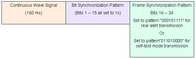
    The structure of the 406 MHz message preamble is provided in the diagram below. The preamble of the 406 MHz digital message allows the receiver-processor to:

    • detect the incoming signal and lock on its frequency, using the unmodulated carrier transmission;
    • lock on the phase and bit timing of the modulation using the bit synchronization pattern; and
    • identify the first data bit of the message using the frame synchronization pattern.

    Therefore, this preamble must be fixed and identical for all Cospas-Sarsat 406 MHz beacons, and encoded according to the format outlined in the figure below.

    Self-Test Mode Preamble

    A 406 MHz beacon can be designed to perform a short self-test. The self-test transmission may consist of a short duration emission of a single burst. If the beacon transmits in the self-test mode, the self-test signal must have a frame synchronization pattern of 011010000 to ensure that the satellite or ground equipment will NOT process this test transmission. This eliminates the risk of a false alert being generated by the self-test burst. In addition, self-test transmissions must be kept to a minimum as they may interfere with “real” 406 MHz distress alerts.

    In the self-test transmission mode the complete test transmission must be limited to one burst only, of a maximum duration of 440 ms for a short message or 520 ms for a long message. If a 440 ms transmission is used for a beacon encoded with the long format message, the message should be truncated without changing the format flag (bit 25).

    Structure of Message Preamble

    preamble


  • 2014-03-21 Costly Chopper Prank

    Crowds gathered at a cliff in New South Wales, Australia, to watch pilot Richard Nest and his crew home in and land in response to what turned out to be a prankster’s distress beacon signal. The beacon, likely stolen from a vessel, was activated and thrown from the Forster breakwall.

    Rescuers had to retrieve and shut off the beacon to prevent disruptive messages from continuing to alert satellites and distract commercial aircraft.

    The “malicious prank” falsely mobilized the three-man Westpac Rescue Helicopter crew and local Marine Rescue personnel, costing taxpayers up to $8000.

    Read more here:
    http://www.greatlakesadvocate.com.au/story/2058632/costly-chopper-prank/?cs=445

This site is registered on wpml.org as a development site. Switch to a production site key to remove this banner.